
Lightning Fast Shipping
Old-Fashioned Customer Service
Competitive Prices & Qty Discounts
Commercial Grade Products
My Cart Id is 88894174
You have no items in your shopping cart.
RSS

Blog posts of '2026' 'September'

Twilight Trim

Permanent eave lighting · Installer resource

A Twilight Trim installation looks effortless when it is finished. Getting there takes a measured, documented plan before the first channel is cut.

Twilight Trim is a permanent, low-voltage lighting system built around individually addressable RGBW LED dots mounted in a low-profile channel under the eave. From one app, the same install delivers everyday white architectural lighting, holiday and game-day color, and animated scenes all year.

This guide walks professional installers and lighting contractors through the job in six steps: four to plan it, two to install and hand it over.

Jump to a step

Two-story home at dusk with multicolored Twilight Trim LED dots outlining every roofline, gable and porch eave

Part 1

Plan Your Project

Almost every problem on a permanent lighting job traces back to planning. These four steps catch issues on paper, where they are cheap to fix.

A run that comes up short, a controller with no signal, an animation that runs the wrong way around a corner, a client who pictured something different: all of these start in planning. Treat your plan as a working document. It becomes your pricing basis, your order, your install map and, at the end, part of the record you hand to the homeowner.

1

Step 1 of 6 · Plan

Define the scope and the look

Start with a design conversation before you pull out a tape measure. Walk the property with the client and agree on:

  • Coverage. Front elevation only, or the full house? Which features matter most: peaks, gables, porches, garage lines?
  • Budget. A clear number early lets you offer phased options instead of redesigning later.
  • Finish color. Match the channel to the trim or fascia so the system disappears in daylight.
  • Mounting profile and light wash. Where the channel sits, and at what angle, changes how much light hits the wall versus the ground.

Arches and curves deserve their own conversation. Mounting closer to the edge, or using an angled profile, changes how the dots read on a curve. Show an example or do a quick mock-up rather than promising a result.

Line drawing of a basic U-shaped mounting channel

Basic

Line drawing of a backer channel with a flat mounting flange

Backer

Line drawing of a chase channel with room for cable

Chase

Line drawing of a 45-degree angled channel

45°

Line drawing of a low-profile Z flashing channel

Flash

Line drawing of four mounting clips

Clips

Channel profile and mounting position shape how much light washes the wall versus the ground.

2

Step 2 of 6 · Plan

Measure and map every run

Accurate field measurements are the foundation of the whole job. Complete them before you give final pricing or place an order. Aerial imagery is fine for a ballpark quote, but it misses returns, soffit depth changes and obstructions.

Work from a photo or simple elevation drawing of each side of the house and give every run its own label (A1, A2, B1 and so on). For each one, record:

  • Measured length
  • Start and end points
  • Corners, returns and other transitions
  • The cable path back to the controller, including any gaps the run must jump

Mark the direction data will travel along each run so animations flow consistently and adjacent runs never appear to chase each other the wrong way.

Craftsman-style roofline with dashed lines marking each measured run along the gables and eaves, with end marks at every start and stop point
Measure each run between clear start and end points, including short returns and porch eaves.

Example layouts

These sample homes show how a roofline is split into zones, with jumper cables routed back to a single control box. Key: red = Zone 1, green = Zone 2, blue = jumper cable.

Single-story craftsman home with three gables marked green for zone 2, the long lower eave marked red for zone 1, and blue jumper cables leading to the control box beside the garage
Sample A: single-story roofline with two zones. The control box sits at the lower right, and a jumper cable bridges the zones across the gable peak.
Two-story farmhouse with the upper gables and eave marked green for zone 2, the porch eaves marked red for zone 1, and blue jumper cables leading down the right corner to the control box
Sample B: multi-peak roofline with independent zones along each ridge line and separate routing for each zone.
3

Step 3 of 6 · Plan

Identify site constraints and access

Before you commit to a price, walk the job with installation day in mind. Look for anything that affects how your crew reaches the eave, where equipment can stand and what the channel mounts to.

Ground access

Landscaping, slopes, decks, fences, pools and tight side yards all limit where ladders or lifts can be set up safely.

Roof and interior access

Note roof pitch, material and condition, and whether you need attic, garage or interior access to route cable or reach power.

Façade construction

Wood, vinyl, stucco, brick and stone each call for different fasteners and prep. Mark material changes along a run.

Obstacles and season

Gutters, downspouts, cameras, fixtures and trees can interrupt a run. Plan around weather and daylight.

Write down the solution for each constraint. If an obstacle changes the scope, such as skipping a section, adding a jumper or needing a lift, explain it to the client before the order is placed, not on install day.

Choose access for the site, not by habit.

Select ladders, lifts or roof access for each work area based on the conditions you documented, and follow applicable fall-protection and height-safety requirements.

4

Step 4 of 6 · Plan

Build the materials list

Place the controller first

Every system needs a control box. Choose a spot with a suitable power source, room to service it later and a Wi-Fi signal you have actually tested at that spot. Because runs are built from the controller outward, its location drives cable paths and data direction for the whole layout.

Count the components

  • LED dots for each run, based on measured lengths and centered spacing
  • Mounting channel in the chosen profile and finish
  • Jumper cables for gaps, corners and the path back to the controller
  • Power injection for any run over 165 dots
  • Fasteners, sealant and grommets suited to the façade materials
Line drawing of a single RGBW LED dot on its cable

LED dots

Line drawing of the controller box with four output cables

Control box

Line drawing of a power injection box with two cables

Power injection box

Key planning numbers

165

dots max per run before power injection

330

dots max per run with power injection

9″

spacing between channel holes

18 ft

jumper length that needs a signal booster

0.5 W

per dot on a 24V DC system

10%

minimum extra mounting trim

Plan for waste and surprises.

Order at least 10% extra mounting trim to cover corners, miter cuts and centering segments. Add a few short dot segments and spare jumpers so a small field change does not stop the job. One control box runs the whole system.

Printable planning checklist

Use one row per run or segment and keep the completed sheet with the job file.

Download the Planning Checklist (PDF)

Twilight Trim run planning sheet
Run ID Location Measured length Mounting type Cable path Controller / zone Proposed parts Review notes
A1 Front, left rake            


Turn your measurements into a parts list

Enter your runs and mounting choices to get an approximate materials estimate, then check it against your plan.

Estimate Your Materials

Part 2

Prepare and Install

With an approved plan and materials on hand, the install follows the same logic: organized, from the controller outward, with checks along the way.

5

Step 5 of 6 · Install

Stage, mount and test

Here is what happens at each stage. For fastening details, wiring connections and component limits, follow the manufacturer’s installation instructions for the exact products you are installing.

Power off before you connect.

Make sure power is off before connecting any cables. Power up to test only after the connections for that section are complete.

Stage 1

Stage and finish components

Confirm every item on the materials list has arrived before you schedule. If the channel is being painted to match the trim, finish it ahead of time. Pre-cut and label pieces by run ID at ground level.

Stage 2

Gather tools and access equipment

A miter saw with a fine-tooth blade for aluminum, powered driver and drill, tape, cutters, fish tape, fasteners for each façade, sealant, grommets, touch-up paint, plus the access and fall-protection equipment the site requires.

Stage 3

Assemble and mount

Start at the controller and work outward along the planned data direction. Center the dots within each segment so spacing looks balanced corner to corner, and use spacers or a jig for consistency.

Stage 4

Test as you go

Once a section’s connections are complete, power it up briefly to confirm every dot responds. One bad connection is far easier to find now than on a finished house.

Stage 5

Pair and configure the app

Download the Spektrum+ app, sign in, pair the controller and set up zones. Load a few scenes and schedules with the client in mind. App guide (PDF)

Smartphone showing the Twilight Trim app with a grid of individually colored dots and a color picker
Two installers in hard hats and safety vests fastening mounting channel under the eave of a gray-sided home
Work outward from the controller, fastening channel to suit the façade material.
Close-up of a single clear LED dot seated flush in a white aluminum mounting channel
Dots sit flush in the channel, so the system nearly disappears in daylight.

Manufacturer installation instructions (PDF)

6

Step 6 of 6 · Install

Finish with a clean handoff

Installer shaking hands with a homeowner in front of a finished house

A permanent system stays with the home for years, so the last visit sets the tone for referrals and future service calls. Before you leave:

  • Inspect the finished work in daylight and after dark: straight runs, consistent spacing, sealed penetrations, touched-up cuts, tidy cable.
  • Demonstrate the controls. Have the homeowner turn the system on, change a scene and adjust a schedule on their own phone.
  • Hand over the materials record: your run map, the completed planning sheet and the parts list, so future repairs or extensions match.
  • Document support information: who to call, product details and any warranty paperwork that applies.

Ready to Plan Your Twilight Trim Project?

Estimate your materials and add everything to your cart in one place, or talk to the Novelty Lights team about your layout.

Shop Twilight TrimGet Help Planning Your Project
What Does "Retrofit" Mean in Holiday Lighting?


Replacement Bulb Guide

What Does "Retrofit" Mean in Holiday Lighting?


How to find replacement bulbs that fit the stringers you already own.

The word retrofit may sound technical or a little dated, but the meaning is simple. A retrofit bulb is a replacement bulb designed to fit a light string or socket you already own.

For example, you can remove older incandescent C9 bulbs from a compatible stringer and replace them with energy-efficient C9 LED bulbs. You keep the existing wire and sockets while upgrading the bulbs.
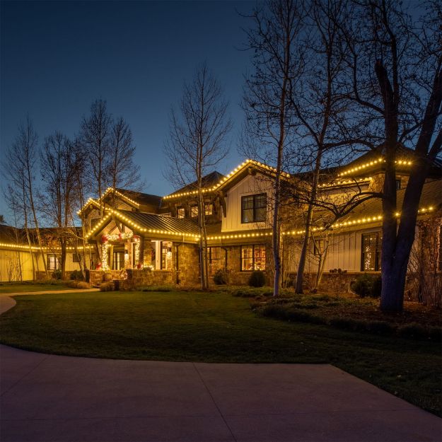
Warm white replacement bulbs installed on a home

Understanding Bulb Base Sizes

The bulb's base is the threaded metal portion that screws into the socket. You may see it called an Edison screw, but that is simply industry jargon for the familiar screw-in base used on typical light bulbs.

The letter "E" stands for Edison screw. The number indicates the base's approximate diameter in millimeters.

Base Size Diameter Common Bulbs
E12 Candelabra 12 mm, or 0.47 in C7, G30, and some G40 bulbs
E17 Intermediate 17 mm, or 0.67 in C9 and many G50 bulbs
E26 Medium 26 mm, or 1.02 in S14 patio bulbs and standard household bulbs

Important: Bulb shape and base size are different. In bulb names, C means cone or candle-shaped, G means globe-shaped, and S means straight-sided, which is commonly called a sign-style bulb. The number that follows the letter identifies the bulb's nominal size. Because the numbering system can vary by bulb family, it should not be used to determine the socket size. E12, E17, and E26 describe the screw base that must match your stringer. Some bulb shapes, including G50, are available with more than one base size, so always check the product specifications.

Side-by-side size comparison of C9 and C7 replacement bulbs

C9 bulb on the left and C7 bulb on the right

How to Find the Right Replacement

  1. Unplug the stringer and remove one bulb.
  2. Look for a label on the plug, wire, socket, bulb, or original packaging.
  3. Measure across the threaded metal base. About 12 mm (0.47 in) is E12, 17 mm (0.67 in) is E17, and 26 mm (1.02 in) is E26.
  4. Check the electrical ratings. Confirm the voltage and make sure the total load stays within the stringer's wattage and amperage limits.

Retrofit bulbs are intended for stringers with removable, screw-in bulbs. They generally do not apply to sealed mini-light sets with permanently attached bulbs.

Still not sure? Take a clear photo of the bulb, threaded base, empty socket, and stringer's label. Send those details to the Novelty Lights team, and we can help identify the correct replacement.



Find the Right Replacement Bulbs


Match the base size and electrical requirements to your existing stringer, then choose the bulb shape, color, and style you want.
